Testing Arc Flash Relays with the MTS-5100
Purpose
The purpose of this document is to provide instructions on how to test arc flash relays using an off-the-shelf camera flash. This testing procedure will describe how to measure the time between activation of the flashbulb and the trip of the arc-flash relay. The application guide references the MTS-5100 hardware, but it applies to the MTS-5000 equipment as well.
Requirements
- MTS-5100 testing platform with firmware 2.05.02 or greater
- Test lead kit
- Cactus KF 36 camera flash or similar (see Figure 1)
- Detachable sync cord (modify the camera end with banana plugs)
- GPS 85 ft. extension cable (optional)
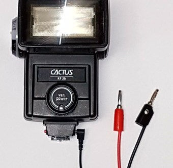
Figure 1, Camera flash with modified shutter cord
Equipment Wiring
The MTS-5100 series testing platform can measure and evaluate the trip time of an Arc Flash Relay (AFR) that is configured to trip via light detection or via light detection supervised with current flow. In this example, the light sensor of the AFR will be activated by triggering the camera flash via OUTPUT 1 contact of the 5100. At the same time, OUTPUT 1 activates INPUT 1 of the 5100 to record the exact time that the camera flash was triggered.
Therefore, OUTPUT 1, INPUT 1 and the terminals of the camera flash are connected to each other in parallel (see Figure 4 below).
NOTE: For convenience, you may use the GPS 85 ft., cable included in the accessory kit, as an extension cable between the camera flash and the MTS-5100 unit. To use the GPS cable, you will need one dual-banana jack to female BNC adapter and one female BNC to dual-banana plug adapter (not supplied) to mate the GPS cable with the modified shutter cord and the 5100 INPUT 1 contact.
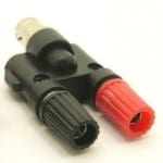
Figure 2 Dual-banana jack to female BNC adaptor
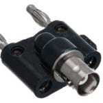
Figure 3 female BNC to dual-banana plug adaptor
If current is used to supervise the light sensor on the AFR then connect one of the current output channels of the 5100 to the corresponding current input of the AFR. In this example, current output I3 terminals of the 5100 unit is connected to the Phase C current input terminals of the AFR. Normally, current on one phase of the AFR is sufficient although three-phase current can be applied as well.
Finally, the OUT1 contact (trip signal) of the AFR is directly connected to the 5100 INPUT 2 contact.
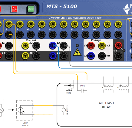
Figure 4, Test connections with TRIP signal mapped to OUT1 output on AFR
Alternatively, we might be testing an AFR that uses a high-speed output (HSO) contact to issue a trip signal. In this case, the AFR HSO1 output, 5100 V4 DC source, and the 5100 INPUT 2 contact are connected to each other in series (see Figure 5 below). The 5100 INPUT 2 contact must be configured as a wetted input contact to detect the state change of the AFR HSO1 output.
NOTE: It is recommended to use the 5100 V4 DC source when monitoring an HSO contact because the “off” state leakage current of some devices could activate a ‘Dry’ type input contact.
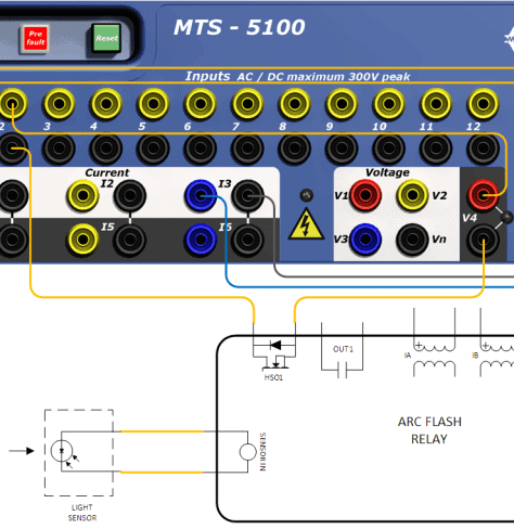
Figure 5, Test connections with TRIP signal mapped to HSO1 output on AFR
5100 Test Configuration
This section describes the necessary settings required to construct a test plan using the onboard 5100 software. Start by configuring the Prefault state within the Manual Test Menu. The Prefault state is used to simulate normal operating conditions prior to the simulation of the arcing fault. It should be configured to output current that is below the overcurrent trip threshold (secondary amps) of the AFR. Given the wiring example in Figure 4 current channel I3 is configured to output 2 A in the Prefault state. The Maximum Duration for the Prefault state is set to 2 seconds after. During testing the Prefault state will be on for 2 seconds and then automatically transition to the “Fault” state. To enable the Maximum Duration timer, press the [F4] Advanced Settings function key and set the Maximum Fault Duration Enabled setting to Seconds (see Figure 9).
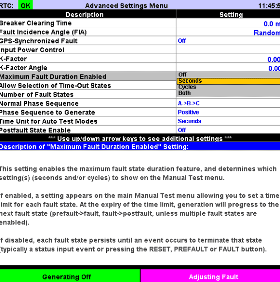
Figure 6, Configuring the Prefault state
If testing an AFR which uses a solid-state output for the TRIP signal (as illustrated in Figure 5) adjust the V4 (DC) voltage output to match the voltage of the station/switchgear DC control bus. To make the V4 (DC) field adjustable press the [F3] Configure Amplifiers function key in Figure 6 to access the Amplifier Configuration Menu (see Figure 7 below). From here press the [F6] Allow V4 Adjustment Function Key to select the ‘Yes’ option. This will take you back to the Manual Test Menu and set focus to the V4 (DC) field where the set point can be adjusted. From here press the [F7] V4 DC Off/On button to turn on the V4 (DC) source.
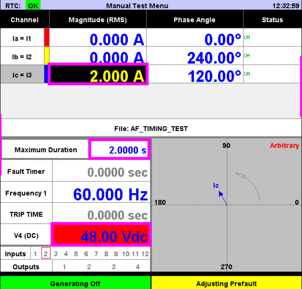
Figure 7, Adjust the V4 voltage (optional)
In the Manual Test Menu, enable adjustment of the “Fault” state by pressing the [F10] State key so that the ‘Fault’ option is selected. If the AFR is operating on current as well as light, then set the appropriate current channel(s) if applicable to a current value that is above the overcurrent trip threshold (secondary amps) of the AFR.
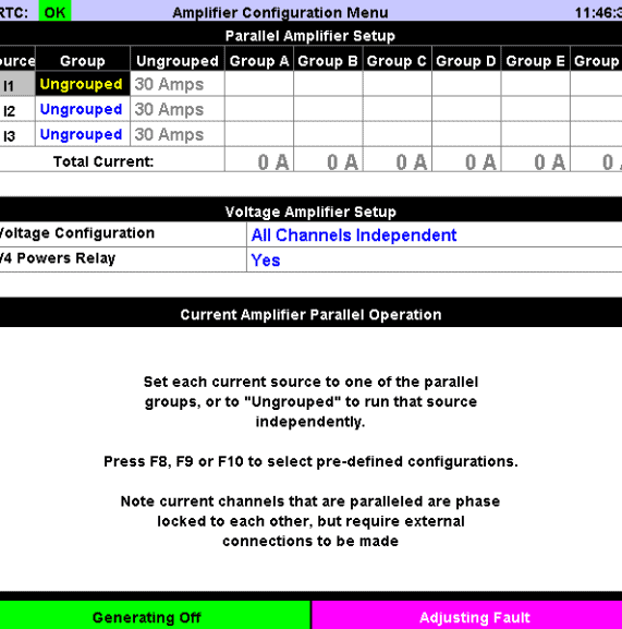
Figure 8, Configuring the “Fault” state
Set the Maximum Duration timer for the “Fault” state to 1 second which allows for a sufficient time for the AFR to trip and complete the test as shown in Figure 8.
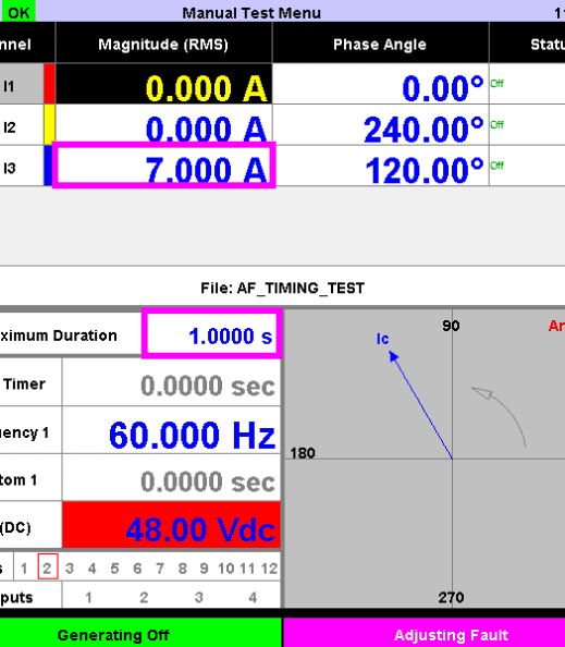
Figure 9, Enable the Maximum Fault Duration timer
From the Advanced Settings Menu, you can press the [F2] Set up I/O and Timers function key to access the Input Setup Menu. The 5100 INPUT 1 contact is being used to determine exactly when the flash is triggered by OUTPUT 1 contact of the 5100. Set the INPUT 1 / Type field to ‘Dry’ since only the state of 5100 OUTPUT 1 contact is being monitored. The 5100 INPUT 2 contact is set to the ‘Wet’ type if monitoring a solid-state output from the AFR as in Figure 5. If this is the case, set the 5100 INPUT 2 contact threshold level between 60-80% of the V4 (DC) setting. Otherwise, the 5100 INPUT 2 contact can be set to ‘Dry’ if monitoring a relay output contact that is not wetted.
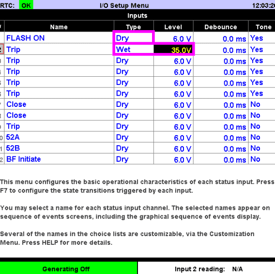
Figure 10, Configure input contact mode and thresholds
Next, configure the input activated fault state transitions by pressing the [F7] Configure Fault State Control function key. Activation of INPUT 1 (relabeled as FLASH ON in Figure 11) should have no effect on fault state transitions. Disable fault state transitions for the 5100 INPUT 1 contact by setting the INPUT 1 / Enable In field to ‘Postfault’ and Input 1 / Go To field to ‘Same State’. Activation of the 5100 INPUT 2 contact due to the AFR tripping will end the test. As such INPUT 2 / Enable In field is set to ‘Fault’, INPUT 2 / Go To is set to Postfault and INPUT 2 / When field is set to ‘Rising’. With these settings, the MTS-5100 will transition to the Postfault state only on the rising edge of the 5100 INPUT 2 contact once it is activated in the “Fault” state.
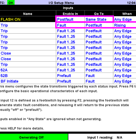
Figure 11, Configure input activated fault state control
In the “Fault” state the MTS-5100 will inject the overcurrent and activate the camera flash to simulate the arc-flash event. To activate the camera flash, the 5100 OUTPUT 1 contact shall be activated within 6 ms of entering the “Fault” state. To ensure proper setup press the [F8] Configure Outputs function key (highlighted in Figure 11), to view the output contact configuration of the 5100. By default, OUTPUT 1 / Function is set to ‘Fault’ as required for the application.
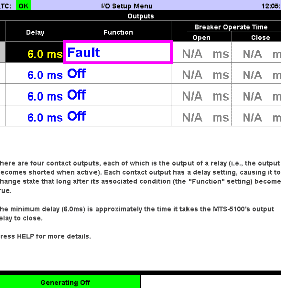
Figure 12, Configure OUTPUT 1 (flash trigger)
A custom timer is used to measure the time between activation of the camera flash (monitored via INPUT 1) and activation of the AFR TRIP output (monitored via the 5100 INPUT 2 contact). This timer is configured by pressing the [F9] Configure Timers and Counters function key in the I/O Setup Menu. In Figure 12 Timer 1 is given the name ‘TRIP TIME’ and is configured to start when the 5100 INPUT 1 contact is asserted. As such, Timer 1 / Start / Event is set to ‘Input 1’ and Timer 1 / Start / When field is set to ‘On’. Similarly, Timer 1 is configured to ‘Stop’ when the 5100 INPUT 2 contact is asserted.
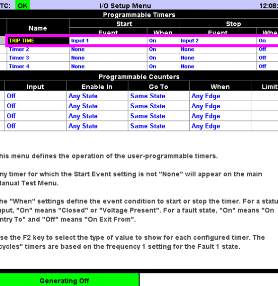
Figure 13, Configure the “TRIP TIME” timer
The configuration described in this application note is available in the MTS-5100 test plan file “AF_TIMING_TEST.manualTestSettings”. Note that the set point of the V4 (DC) field, in the Manual Test Menu, cannot be saved in the .manualTest test plan file. Therefore, the correct value for V4 (DC) needs to be verified and set after the file “AF_TIMING_TEST.manualTest” is loaded. Likewise, the state of the [F7] V4 DC Off/On key cannot be saved in a .manualTest test plan file. Therefore, if required, the [F7] V4 DC Off/On needs to be turned on manually prior to commencing the test.
Testing Procedure
- Wire the camera flash, MTS-5100 unit and AFR per either Figure 4 or Figure 5 above, depending on the type of relay contact mapped to the TRIP signal.
- Apply the appropriate configuration to the MTS-5100 by following instructions in the previous section or loading the file AF_TIMING_TEST.manualTest into the test system and making appropriate changes if necessary.
- If the arc-flash TRIP output is wetted:
- Make changes to the V4 (DC) field in the Manual Test Menu, as described in the previous section.
- Activate the V4 output by pressing the [F7] V4 DC Off/On function key in the Manual Test Menu.
- In the Manual Test Menu, press the [PREFAULT] button to initiate the test.
- Once the test sequence is complete, the Timer 1 field (re-labelled as ‘TRIP TIME’ in “AF_TIMING_TEST.manualTestSettings” file), in the Dynamic Display Area of the Manual Test Menu will show the timing results of the test.
- After the test is complete press the [F6] Test Report function key followed by the [F10] Save function key to display the Report Detail Entry menu.
- Set the Expected Unit field to ‘seconds’ and set the Expected Value field to the ideal operating time of the AFR.
- Set the Tolerance Unit field to ‘seconds’ and set the Tolerance Value field to the tolerance specified in the AFR manufacturer’s specifications.

