Purchasing Shell-Form Transformers
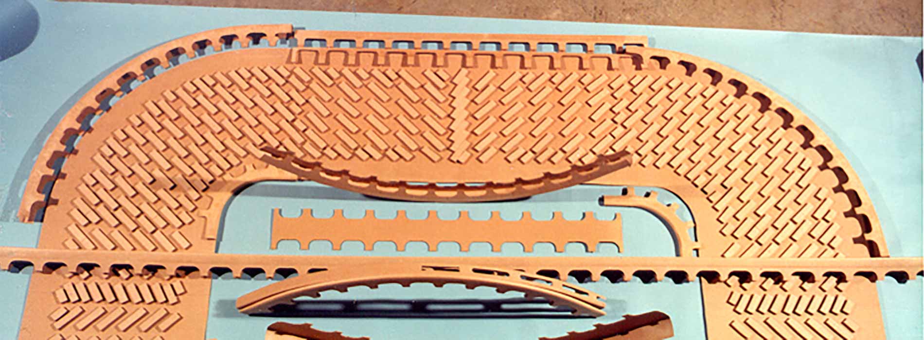
When purchasing a power transformer, a choice between two main construction technologies available on the market must be made; whether to purchase the more commonly available core-form construction or to opt for a shell form transformer. The shell transformer was developed by William Stanley in 1886 by turning out the earlier Lucien Gaulard and John Dixon Gibbs “induction coil” design to produce the first reliable commercial shell form power transformer. This development led to George Westinghouse being granted US Patent 366362A for the first shell transformer on July 12, 1887 based on the work of William Stanley.
Since 1887, shell transformer technology has evolved by continuous refinement and advancement by many manufacturers across the globe to offer unique transformer application solutions:
Through Fault Withstand Capability
- The shell design reduces the total short circuit stresses experienced within coil groups by increasing the number of coils groups in each winding.
- The short circuit forces within successive coil groups are in the opposite direction tending to keep the phase in compression during a fault.
- Shell form insulation structure experiences lower stress levels during a short circuit fault due to the large coil area.
- The coil groups are supported by the core and tank to form an integral system to resist short circuit forces.
Insulation System & Effect of Over-voltages
- Shell coil systems have very high coil-to-coil capacitance and low coil-to-ground capacitance, consequently improving impulse voltage distribution.
- Since the ratio of coil-to-coil to coil-to-ground capacitance is relatively large, the voltage distribution within coils is nearly linear even with fast rising surge voltages.
- Due to the near linear impulse voltage distribution, oscillations developed with coils and windings are reduced and the period of oscillation is relatively long, allowing transient voltage to decay to limit voltage increase from the reflected wave.
De-energized Tap Changer Design Flexibility
- De-energized taps can be added to the low voltage and even tertiary windings with relative ease to facilitate spare transformers with multiple low voltage ratings.
- For autotransformers, de-energized taps can be arranged in a boost-buck to reduce the number of tap leads and the number of turns in the tap section of the winding.
Design Flexibility
- In two or three winding transformers, tap sections will be in the neutral end of the high voltage winding which is the lowest BIL point of the insulation structure.
- For single phase transformers, the tank and core construction makes transportation and installing in both horizontal and vertical position possible.
- Very low impedances can be met by the interleaving of coil groups without compromising the transformers short circuit integrity.
- Large values for the air core reactance are achievable that help reduce inrush currents.
Doble has a team of transformer design experts that regularly review transformer selection criteria on behalf of our customers. Rely on our experts as an extension of your team when you need these critical services.
Contact Doble for more information about our transformer consulting and testing services.


