MTS-5100/MTS-5000 Software Version 2.05 Features
Learn about some of the significant new features in Software Version 2.05 for the MTS-5100 and MTS-5000 Protective Relay Testing Systems.
Table Of Contents
New three-phase differential productivity mode
What It’s For
How It Works
Supported Relays
Improvements to 21: Distance (Impedance) Relay Test Mode
Menu Layout Changes
Improved support for quadrilateral distance elements
Ramped and Pulsed Reach Tests
MHO Settings Format for the GE D60
Adjustable Ramp Rate in the MHO MTA Test
Improvements to 50: Instantaneous Overcurrent Relay Test Mode
Improvements to 51: Time Overcurrent Relay Test Mode
Fault-state control for complex test sequences
Enhanced reports in autorecloser productivity mode
Ability to combine voltage channels in series
Simplified method for selecting angle display format
Little Things
USB keyboard emulation of the RESET, PREFAULT and FAULT keys
Diagnostic file save
View help for the selected setting
Improvements to IEC 61850 / GOOSE functionality
Productivity modes show all menus even in “manual”
Custom user-displayable values
Report “Save” key hidden until you have run a test
MTS-5×00 Remote Console and RapidReporter can now work together
In Conclusion
New Three-phase Differential Productivity Mode
What It’s for
This mode is optimized for testing three-phase differential relays, including:
- Generator differential relays.
- Transformer differential relays.
It was a beta-test feature in earlier versions, but Version 2.05 it is available to all users. It supports a selection of popular relays, and also has a “plug-in” mechanism to add more. If you are testing a relay that is not supported, technical support staff may be able to create a plugin installer to add support for a new relay, rather than wait for the next major software release.
How It Works
The major components of this new mode are:
- Accepting setting values to describe the system under test, which comes from equipment nameplates, schematics / wiring diagrams and the configured relay settings.
- Modeling the system under test, including calculating the CT currents that would be presented to the relay in the actual system.
- Performing the same calculations as the relay, to indicate the differential and restraint currents that should be used by the relay for the restrained and unrestrained elements.
For example, here is the settings screen for the SEL-387 relay:
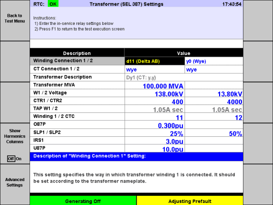
In this example the transformer nameplate says winding 1 is D11 (Delta AB) and winding 2 is Wye, so those settings are entered on the top line. Just below that, we’ve indicated that the CTs both use Wye connections, and the transformer description provides the IEC nomenclature “Dy1” for this transformer.
Some settings can only be derived from the relay configuration, and those share a name with the corresponding settings in the SEL-387 relay. The software has calculated the winding 1 and 2 tap currents, and internally it has configured a mathematical model of the transformer and CTs.
Back in the test screen, note the characteristic curve according to the relay settings, and as the winding currents are adjusted, the testing system’s current outputs (upper half of the screen) simulate the currents that would be presented to the relay with those actual in-winding current levels.
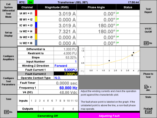
Since winding 1 is delta, current present in one phase of that winding appears on two of the CTs, so the testing system’s current outputs do likewise. The testing system calculates the differential current (1.333 per-unit) and the restraint current (4.000 per-unit) to plot the phase “a” point on the graph.
Note that in the example shown, there’s another dot on the graph. That is because zero-sequence removal causes differential and restraint current to appear on the non-fault phases (b & c), and the dot shows that those phases might operate before the fault phase. That is what would happen in the real system for a single phase fault, with no currents through the non-faulted phases of the transformer windings. To test that relay, you need to add a bit of prefault current, to reduce the differential current on the non-fault phases so that the faulted phase will always operate first.
The “winding 2 direction” setting may also be used to test the unrestrained element, and turn on harmonics to test harmonic blocking.
Supported Relays
At the time of delivery, Version 2.05 includes support for the following relays:
- SEL-300G Generator Relay, when the E87 setting is “G” (i.e. generator protection).
- GE T60 Transformer Protection System and other GE UR relays that include a transformer differential element.
- SEL-387 Current Differential and Overcurrent Relay.
- SEL-587 Current Differential Relay.
- SEL-787 Transformer Protection Relay.
The plug-in mechanism means we can add support for more relays between software releases, so let us know if you need support for a differential relay that’s not listed.
Improvements to 21: Distance (Impedance) Relay Test Mode
Menu Layout Changes
In Version 2.04.02 or earlier, to select a relay type in 21-mode, a user would navigate to the relay settings screen and press function keys to select the “settings format” for that relay.
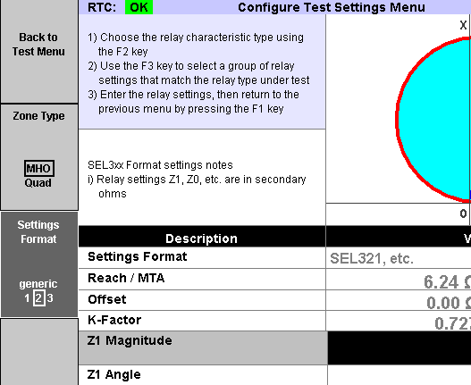
There are new relay types in Version 2.05 and we added some selection screens, which appear when 21-mode is selected.
First select the basic type: MHO, Quad or “Advanced Distance Protection.”
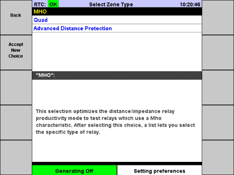
For MHO or Quad, select the specific type of relay. For MHO, the selections are:
- Relay with K0/K-factor settings (SEL).
- Relay with rectangular line settings (SEL-121).
- Relay with polar line settings.
- KD-4, KD-10, KD-11.
- Relay with Z0/Z1 (GE UR).
The first four correspond to the old “generic” and settings formats 1 through 3. The fifth one is new in Version 2.05 and is optimized for testing the MHO distance elements in the GE D60 and other GE UR-series relays.
Improved support for quadrilateral distance elements
When you select “Advanced Distance Protection” on entry to 21-mode, it’s equivalent to the “Quad” zone type in Version 2.04. It allows a user to specify any type of characteristic shape without being tied to a specific brand or model of relay.
When “Quad” is selected in Version 2.05, the user is presented with a list of relays. Two popular quadrilateral distance relays are supported:
- SEL relays, including the SEL-311C.
- GE UR relays, including the D60.
Like the three-phase differential test mode, those relays are defined using plugins. If the relay isn’t on the list, Manta technical support staff may be able to create a plugin prior to the next major software release. SEL relays enable MHO and quad elements for the same zone, so the plugin for those relays supports testing the MHO characteristic, the quad characteristic or combined MHO/quad.
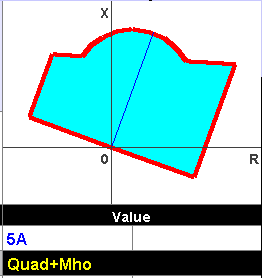
Settings are entered using the same setting names, etc., as the relay. The testing system calculates the quadrilateral shape and for ground distance elements it computes the zero-sequence (K) factor.
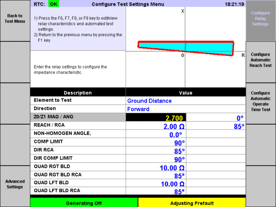
Quadrilateral-specific automatic tests are provided. Use the reach test allows to specify the angles at which to test and produce a report containing the measured reach at each point.
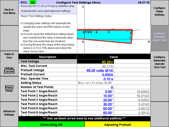
The operate-time test works the same way as it does for MHO. Specify points within the characteristic shape to test the operate time and the report includes a table of the measured times.
There is a subtle difference between the MHO and quad features. For MHO relays, use the Fault Type key (F8) on the test screen to select ground distance or phase distance:
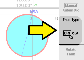
If the phase-to-neutral fault type is selected, the assumption is that it is a ground distance relay. Injected faults are single-phase, and the calculated zero-sequence factor (K-factor) is used to calculate impedance. If the phase-to-phase fault type, the relay is assumed to be a phase distance relay. Phase-to-phase faults are injected and the K-factor is not used. When you select a three-phase fault, balanced conditions are injected. The K-factor cancels out in the math, so three-phase faults work for either ground distance or phase distance relays.
For quadrilateral distance elements, select the element type (ground distance or phase distance) in the “Configure Test Settings” screen. Most quadrilateral relays use different settings for ground and phase distance, and the configuration screens adapt so that the user knows which settings to enter for a particular configuration. A side effect of this difference is that you can, for example, test the response of a phase distance element to a three-phase fault. The relay simulation and impedance calculations don’t change, so they still match what the relay should be doing in each case. Only the injected fault type changes.
Ramped and Pulsed Reach Tests
In Version 2.04, 21-mode automatic reach tests use a pulsed binary-search method. In Verison 2.05, there is an option to select “ramped” or “pulsed.” The “pulsed” option works as it did in Version 2.04.
The “ramped” option uses a dual-ramp algorithm. At each test angle, the voltage or current is smoothly ramped twice, at two different speeds, in each case noting the point at which the relay operates. The difference in those operate points is used to determine the operating time of the relay, to back it off from the ramp end time. This ensures the reported reach results are precise, even if the relay has a long operate time.
If there is a need to test the reach at which the relay will operate in a particular amount of time (for coordination with other zones, for example), continue to use the “pulsed” method and set the maximum operate time.
MHO Settings Format for the GE D60
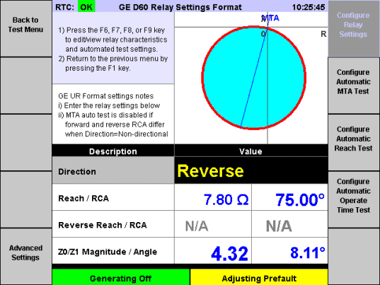
Version 2.04 had four different settings formats for MHO distance relay. Version 2.05 adds a fifth format, for the GE D60 and other GE UR relays. This mode allows testing of forward, reverse and non-directional configurations, with settings specified in the same format used by the relay.
Adjustable Ramp Rate in the MHO MTA Test
When using the automatic MTA test for a fast zone, a slower zone may operate during each phase-angle ramp. The new ramp-rate setting allows you to speed up the ramp rate so that the fast zone operates before the slow one.
Improvements to 50: Instantaneous Overcurrent Relay Test Mode
This mode provides the ability to specify the expected operate time, rather than assuming zero. Test definite-time relays in this mode, rather than using 51 mode and a custom (flat) curve.
Improvements to 51: Time Overcurrent Relay Test Mode
The ANSI 51 productivity mode in the MTS-5100 and MTS-5000 includes curve data for a large number of relays and standards. If the relay you’re testing is not on that list, you select “Generic Time Overcurrent Relay,” and enter the specific operate-time values for different multiples of the pickup.
In Version 2.05, there is a new feature to install additional curves using plugins, without waiting for the next software release. Manta technical support staff can prepare a plugin file to load on your test system. A new entry “Custom Time Overcurrent Relay Curve” appears in the relay selection menu for 51 mode:
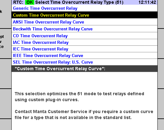
Selecting that choice presents a list of all installed (“custom”) curves that can be used like the standard curves
Fault-state control for complex test sequences
Enable the “Maximum Fault Duration” feature in Manual Test / Advanced Settings:
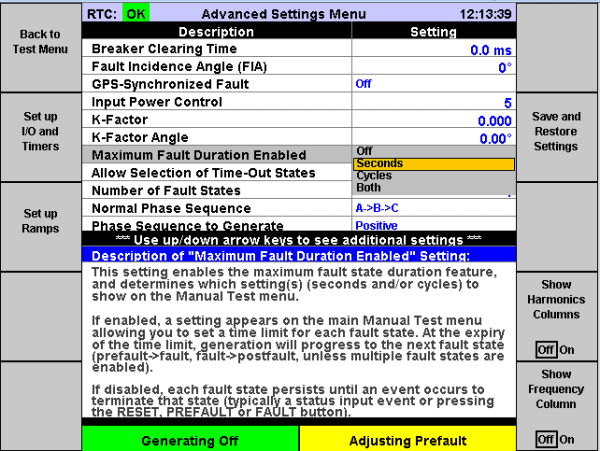
A maximum duration may be set for each fault state in seconds or cycles (“Both” shows both, and adjusting one changes the other).
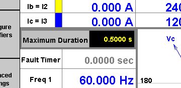
When running a test, if the particular fault state is generating for the specified amount of time, the test system switches generation to the next fault state in sequence. If the time-out expires in prefault, generation switches to fault 1. If there are multiple fault states, fault 2, for example, times out to fault 3, and the last of those goes to postfault (or “off”, if postfault is not enabled).
As an example, you can set up two fault states, with a 1-second timeout on fault 1, and input 1 configured to transition from fault 1 to postfault. If input 1 closes before the 1-second timeout, postfault is generated. If not, generation switches to fault 2, indicating that the relay did not operate.
In Version 2.05 we added a new setting “Allow Selection of Time-Out States.”
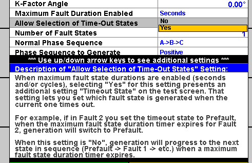
When “Yes” is selected for that setting, the test screen includes a setting called “Timeout Fault State,” for the user to specify which state will be active when the timer expires.
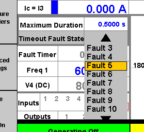
This feature can be useful when configuring very complex tests, such as complicated recloser schemes, using the Manual Test facility.
Enhanced reports in autorecloser productivity mode
The 79: Auto-Reclose Relay Test Mode produces a report including all the reclose times and the lockout time. In Version 2.05, we added the operate times of the relays to that test report.
Ability to combine voltage channels in series
In Manual Test, the “Configure Amplifiers” menu allows set up of parallel current configurations, for a smaller number of currents, but more amps per channel.
In Version 2.05, a new “Voltage Configuration” setting in that menu allows users to easily operate the voltage channels in series.
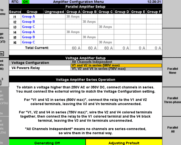
On an MTS-5100, each voltage channel can produce up to 250 VAC. By operating V1, V2 and V4 in series, it is possible to produce a single voltage up to 750 VAC.
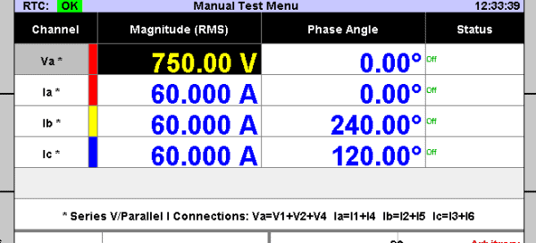
The V4 channel on the MTS-5000 is DC-only, and the V1,2,3 amplifiers can produce up to 150 VAC. On the MTS-5000, operating the V1 and V2 outputs in series allows you to produce up to 300 VAC.
The V3 output is not used in series configurations. This is because V1, V2 and V3 share a common neutral, so there is no way to connect all three of them in a series.
Simplified method for selecting angle display format
As in previous software versions, you can change the way angles are displayed on vector diagrams and in the per-channel phase angle column on the test screen. The old method still works. From the main menu (the one with the Manta logo), press F10 “Setup” and these settings appear (among others):
- “Entry range for phase angles,” with options:
- 0 to +360
- -180 to +180
- -360 to +360
- “Meaning of positive angles,” with options:
- Leading
- Lagging
Using those settings, the MTS-5100 or MTS-5000 can represent angles the same way as the relay being tested, or in the same format as other software or test equipment for which your test procedures were written.
Some users were unclear about how to use those settings or were unaware if the settings. They are power-on values, so they can’t be used to select a different angle format for two different tests, as when you’re testing two different vendors’ relays.
In Version 2.05 we added a new setting in “Manual Test” / “Set up Display” called “Angle Display Format.”
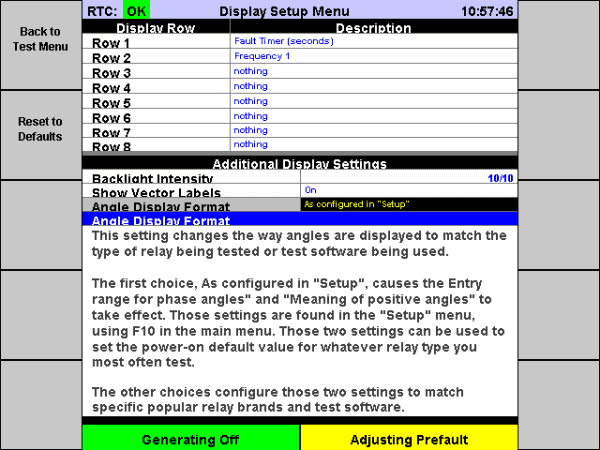
The choices for that setting are:
- As configured in “Setup”
- Uses whatever format selected by the two settings found in the “Setup” menu.
- SEL
- Selects positive=leading and range -180 to +180.
- GE UR
- Selects positive=leading (i.e. negative=lagging) and -360 to 0.
- GE SR
- Selects positive=lagging and 0 to 360.
- Doble RTS™
- selects positive=lagging and 0 to 360.
When a manual test settings file is saved, the new setting is included. When the file is loaded, the angle display format is configured as it was when the file was saved.
Little Things
USB keyboard emulation of the RESET, PREFAULT and FAULT keys
When a user is plugged into a USB keyboard and on a screen where the RESET, PREFAULT and FAULT keys are enabled, those operations can also be performed by pressing R, P and F on the keyboard:
- R stops generation, and if generation is already stopped pressing R clears captured data from the screen (but not from the test report).
- P starts generating the “prefault” state.
- F starts generating the “fault” state (or “fault 1”, if you have enabled multiple fault states). As with the physical FAULT key, pressing and holding F on the keyboard enters the “Static Fault” state, which means that inputs are ignored, and releasing the key goes back to the previous generation state (or turns generation off, if generation was off when you pressed the key). Static fault is useful for pickup testing, when there is a need to dial the current or voltage up and down to find the pickup point, without ending the test the first time the relay’s output closes.
Diagnostic file save
Manta technical support staff may sometimes ask users to send diagnostic information, in order to help understand the issue in question. In the past, that meant accumulating various files using the Files menu, report viewers and sometimes the web interface.
In Version 2.05 we added a new “Save Diagnostic File” key. From the main menu, press F9 “Diagnostics,”and the F3 key is now “Save Diagnostic File.” Save the file either to a USB flash drive or store it locally in the test system for later retrieval. The file includes, among other things:
- A log of actions you took before saving the file: key-presses, setting adjustments, remote commands, etc.
- All the plugin files installed (if there are any).
- The values of all settings.
- The latest report and sequence of events log.
- COMTRADE waveform files.
- Technical information about your system.
- Any captured error files.
- Maintenance logs.
- Calibration data.
Many times the diagnostic file is the only item Manta’s technical support staff requires in order to understand your issue. Save the file right after the issue arises and before powering down the test system. The log it saves will include a full record of what happened.
View help for the selected setting
Many screens have help information at the bottom, describing whichever setting is currently selected. In some screens, though, the help area is omitted to make space for other things. In Version 2.05, you can obtain help for those settings by:
- Navigating to the particular setting using the arrow keys.
- Pressing the HELP key.
- Pressing F8 “Describe Selected Setting.”
A description of the setting appears, along with information about the numeric range, choices available for selection, etc. for the setting.
Improvements to IEC 61850 / GOOSE functionality
The MTS-5100 and MTS-5000 test systems include an easy-to-use facility for testing systems that use IEC 61850 GOOSE messaging. In Version 2.05 we have further expanded on that feature, adding support for some unusual ICD/SCL file formats and allowing more flexibility when configuring GOOSE outputs to publish.
Productivity modes show all menus even in “manual”
In previous software versions, some productivity modes required selection of “auto” using the F7 “Test Type” key before F4 “Configure Test Parameters” in order to adjust settings for the automatic tests. In Version 2.05, you can access those settings even when “Test Type” is set to “Manual.”
Custom user-displayable values
From a test screen, if you press F2 “Set up Display” you can select up to 8 calculated values or settings to show on the test screen, in addition to the standard values (see MTS-5000/5100 Basics: Displaying Calculated Values on YouTube). For example, select “I Unbalance” to show the percent current unbalance. This may be useful when testing an unbalance relay, to see the relay’s operating parameter on the test system’s screen, and so that the percent unbalance at which the relay operated can be included in the test report.
In Version 2.05 we added a mechanism allowing technical support staff to add custom entries to the list using plugins. Please contact technical support if you need a calculated value that isn’t included in the pop-up choice lists.
Report “Save” key hidden until you have run a test
If you load a settings file (or load settings from a report file) then try to save a report before you have run a test, the result selectors can change. That’s because some selectable result values only exist after you have run the test. To prevent this from happening, in Version 2.05 the “Save” key does not appear in the report viewer after loading a file, until you have run a test.
MTS-5×00 Remote Console and RapidReporter can now work together
RapidReporter™ 0.94 or later has a “rerun” feature, allowing you to send the settings from a test report to a connected MTS-5100 or MTS-5000, and after running the test retrieve the results back into the database.
In Version 2.05, you can also use that feature when you are controlling the test system using the MTS-5×00 Remote Console program on your Windows PC. To do that, you need to add the “TCP” command-line argument to the shortcut you use to launch Remote Console. On your desktop (or in Windows Explorer, under “Desktop”), right click “MTS-5×00 Remote Console” and select “Properties.” In the “Shortcut” tab you’ll see a field called “target” (it should be highlighted when you first show Properties). Add tcp to the end of that field, as shown below:
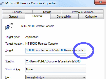
Run Remote Console and connect to your MTS-5100 or MTS-5000. The TCP argument causes the program to listen to TCP port 60000, processing the same commands handled by the test system.
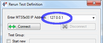
Now in “Rerun Test Definition” dialog for RapidReporter you can enter the IP address 127.0.0.1 (which means the same PC running RapidReporter), and re-run the test the same way you would when connected directly to the test system.
In Conclusion
That was just a brief introduction to the new features in Version 2.06 of the MTS-5100 / MTS-5000 software. We are preparing training material which will dive deeper into some of the individual features. If you need assistance you can contact Doble.
You can download the latest MTS-5000 / MTS-5100 software and related PC software from our customer area, under MTS-5000/MTS-5100 Software.

